Electronics
Our electrical circuit is broken up into five main parts as listed below: The Master, Shot, Motor, Wave, and Middle Limit Circuits
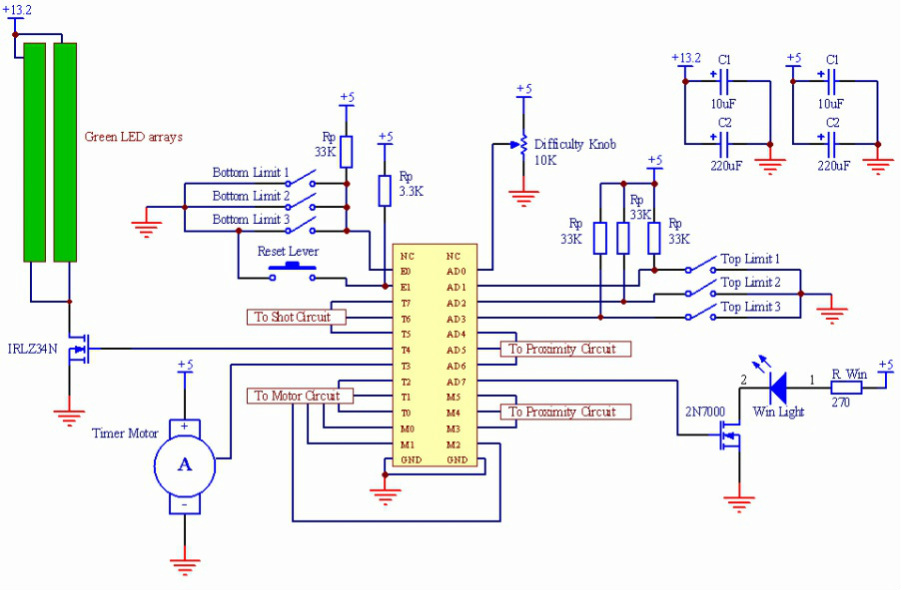
The Master Circuit
This circuit shows all direct connections to the microcontroller and ties the other three circuits together. Displayed components include:
- Difficulty Knob - Allowed users to select the difficulty level.
- Reset Lever - Really more of a button in the end. Started the game after difficulty was selected.
- Timer Motor - Servo motor used to display passage of time. We used a CS-929MG.
- Bottom Limit Switches - Allowed the microcontroller to tell when the monkeys reached the bottom of travel.
- Top Limit Switches - Activated when the monkeys reached the top of travel.
- Green LED arrays - Light up during game play. Consist of green LEDs and resistors in series.
- Win LED - Lights up when the timer runs out and non of the monkeys have reached the bottom. Indicates victory.
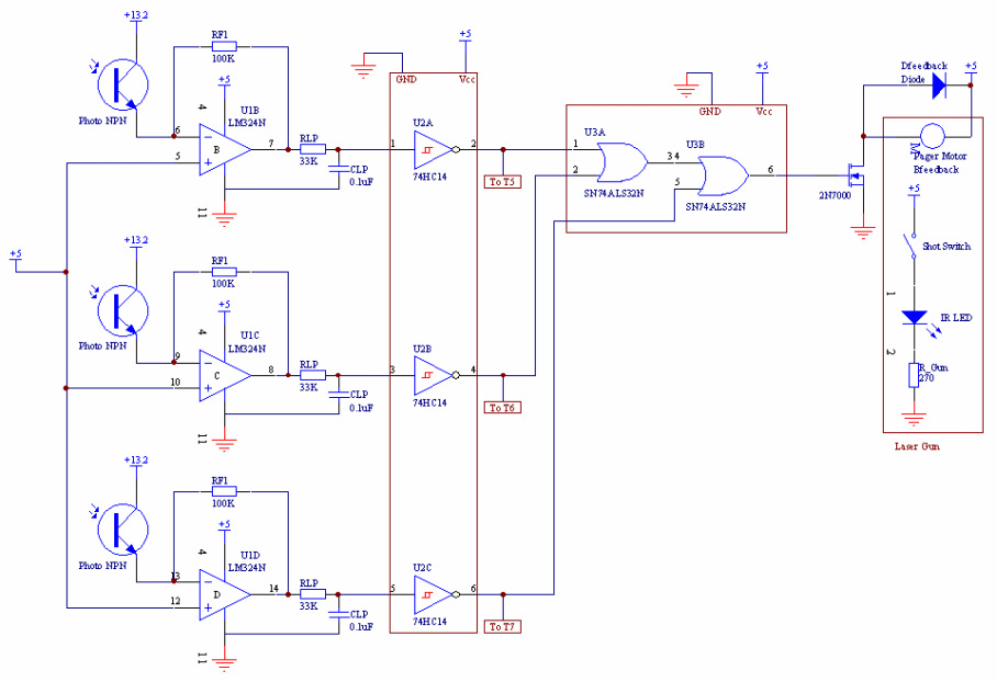
The Shot Circuit
This circuit outlines all electronics related to the IR gun, IR receivers, and user feedback. The flow of logic is as follows:
- First, the shot is fired from the laser gun (switch activated at far right).
- The IR light reaches the photo transistors, generating current in the op-amps and a 0-5V signal at the op-amp output.
- The 0-5V signal is sent through an inverter with a schmitt trigger, cleaning the signal being sent to the pins T5-T7 on the microcontroller
- Hardware feedback activates a pager motor if any of the photo transistors are activated, which is the purpose of the logical OR IC.
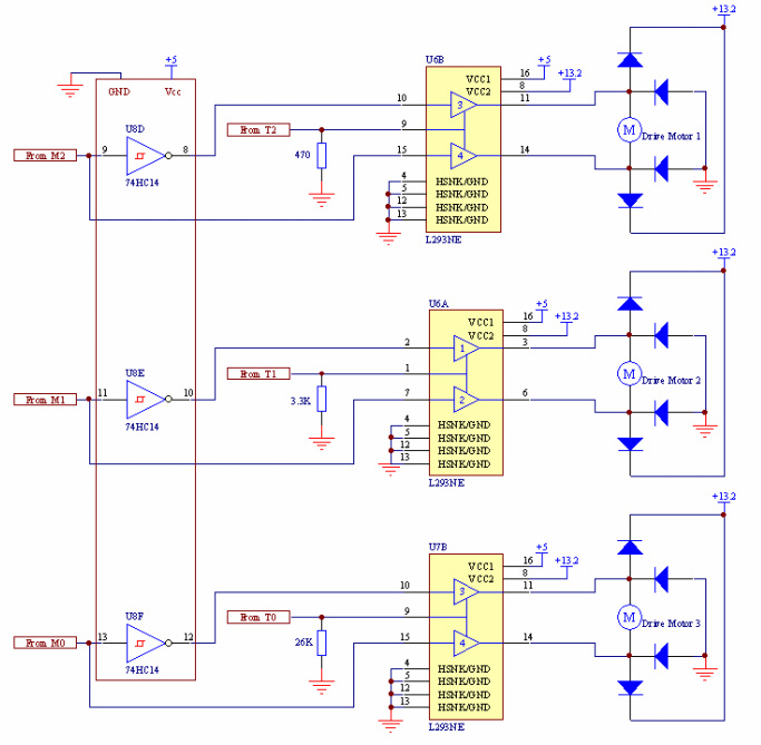
The Motor Circuit
This circuit controls all motor movement. For each motor, one H-bridge was used to control direction and speed. Speed was controlled through Pulse Width Modulated (PWM) signals.
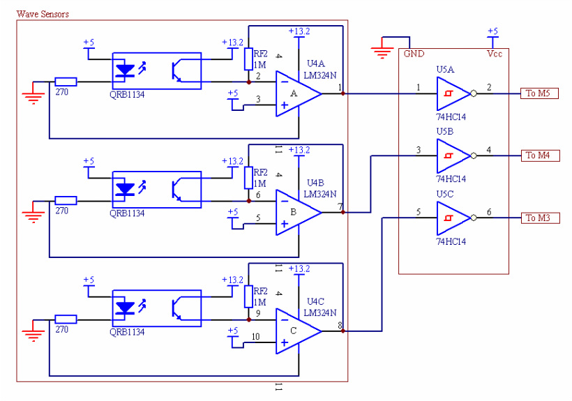
The Wave Sensor Circuit
This circuit controlled all wave sensors used to keep the monkeys away from the bananas. We used tape sensors to detect the user's hand. Tape sensors work by shining IR light and measuring any IR reflection off of close surfaces. On the left was the circuit used to power each tape sensor, and on the right was the set of inverters used to clean the signal through schmitt triggers.
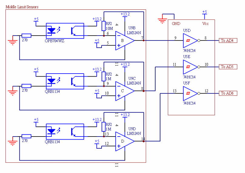
The Middle Limit Switch Circuit
This circuit controlled all middle limit switch sensors used to determine when the monkeys reached the half-way point in their shafts. On the left was the circuit used to power each tape sensor, and on the right was the set of inverters used to clean the signal through schmitt triggers. It is almost identical to the Wave Sensor Circuit layout. One note is that one of our tape sensors was made by a different manufacturer, and therefore needed a different feedback resistor on the op-amp (10M vs. 1M) to tune it differently.